GarmLink PRO-V1 hub passport
This section contains the official manual for the GARM Link PRO-V1 device.
Here, you will find all the essential information about the product — technical specifications, connection diagrams, operating instructions, and warranty details.
The manual is provided in its original form so that you can refer to it whenever you need guidance for maintenance or when contacting the service center.
|
DEVICE PASSPORT
for the IoT Controller
“Garm Link PRO-V1”

LLC “GARM”
420500, Republic of Tatarstan, Verkhneuslonsky District,
Innopolis, Universitetskaya St., 5
Phone: +7 (960) 250-60-00
Website: https://garm24.com/
1. General Information
This document provides the technical specifications, package contents, operating conditions, and warranty obligations for the GARM Link PRO-V1 terminal control and monitoring device (TCMD).
The manufacturer reserves the right to make design or technical modifications aimed at improving the product without prior notice.
All changes will be reflected in the next revision of this passport.
2. List of Abbreviations
Table 1 — List of Abbreviations
|
Abbreviation
|
Description
|
|
TCMD
|
Terminal Control and Monitoring Device — main control and communication unit of the GARM system
|
|
AWS
|
Automated Workstation — operator’s workplace software
|
|
CMS AWS
|
Automated Workstation of the Central Monitoring Station — interface for system monitoring and event management
|
|
GARM PC
|
GARM Software Suite — includes server software, field devices, CMS application, mobile and web clients
|
|
Astra-RI-M System
|
Wireless Fire and Security Alarm System “Astra-RI-M”
|
|
BAT
|
Rechargeable Battery — internal backup power source installed in the TCMD
|
|
LC
|
Loop Circuit (Signaling Line) — connection line for security or fire sensors
|
3. Purpose and Scope
3.1. The Control and Indication Panel (TCMD) is designed to organize security, fire, alarm, emergency, and other types of signaling at a facility as part of the GARM Software Suite (GARM PC).
3.2. The TCMD provides the following functions:
-
Reception of information from ASTRA wireless sensors via the 433 MHz radio channel;
-
Monitoring of the status of wired sensors connected to the TCMD inputs;
-
Encrypted data exchange between the facility and the server through commercial TCP/IP networks (Internet), GSM (GPRS) mobile communication, and wired Ethernet connection.
4. General Information and Features
4.1. The TCMD registers and processes the status of up to 32 wireless sensors of the Astra-RI-M system.
4.2. It ensures data exchange with the CMS AWS and Internet applications through the server using:
-
Primary channel — Wi-Fi 802.11 b/g/n (up to 150 Mbps)
-
Backup channel — SIM card (GPRS/EDGE, GSM)
-
Channel priority: Wi-Fi first, then SIM card
4.3. Configuration and maintenance of the TCMD are performed using the CMS AWS or web applications according to the user manual.
The mobile application can be installed from the app store.
4.4. The external power supply for the TCMD is provided by two independent sources in any combination:
-
From the main power source via a 220/12 V 2 A adapter (DC connector)
-
From a backup 12 V power source via the +12VR- terminals on the board
Continuous monitoring and notification of the power supply status are provided.
4.5. For power redundancy, the TCMD includes:
-
A connector for an internal Li-Ion battery (3.7 V, 1800 mAh) installed inside the housing
-
A connector for an external AGM battery (12 V, 7 Ah) installed outside the housing
4.6. Power Supply Notes
-
The battery connection must be made immediately before applying external power to the TCMD.
-
Startup from a battery alone is not possible. Startup without a battery is allowed.
-
When switching to the internal Li-Ion battery, the TCMD:— Maintains communication via both Wi-Fi and GPRS channels— Powers wired sensors (the “Fault” message is generated)— Does not power wired outputs
-
When switching to the external AGM battery, the TCMD:— Maintains communication via both Wi-Fi and GPRS channels— Powers wired sensors (the “Fault” message is generated)— Powers wired outputs
4.7. The TCMD includes a built-in Touch Memory (TM) input for connecting iButton-standard key readers and/or digital temperature sensors.
TM codes are registered through the CMS AWS and user applications.
4.8. The TCMD is equipped with 8 programmable open-collector outputs (+CN_OUT_x-) with configurable operating modes.
Output configuration is performed through the CMS AWS and web applications.
4.9. The TCMD includes 7 pairs of individually programmable inputs (+CN_ZONE_x-), which can operate in various modes:
-
Output mode (“open collector”) — when powered from +12 V, allows connection of external devices (e.g., Foton-9 siren) for manual or automatic control.Operation logic (“indicator lamp,” “siren,” etc.) is configured via the CMS AWS and web applications.In this mode, the +CN_ZONE_x- terminal is not used and may serve as an “intrusion” or “technical” input.
-
Input mode (“intrusion” or “technical” loop) — allows connection of sensors with a “dry contact” output operating on open/close principle (to +CN_ZONE_x-, 12V-, or 12VR- terminals).In this mode, the +CN_OUT_x- terminal is not used and can be assigned as an output.
-
Input mode (“fire” or “fire with dual triggering”) — allows connection of two-wire alarm loops with fire detectors powered via the loop (to +CN_ZONE_x- terminals).
5. Wiring Diagrams
5.1. Connecting Security Sensors
The zone status is determined by the TCMD by measuring the loop resistance.
Security logic thresholds:
0 ≤ “Alarm” < 3.3 kΩ
3.3 kΩ ≤ “Normal” ≤ 5.6 kΩ
5.6 kΩ < “Alarm”
It is recommended to use the following wiring diagram for security sensors with Normally Closed (NC) and Normally Open (NO) contacts (see Figure 1).

Figure 1. Security Sensor Wiring Diagram
NC — Normally Closed security sensor contact
NO — Normally Open security sensor contact
Rterm — Terminal resistor, 4.7 kΩ ±5%
5.2. Connecting Fire Sensors
5.2.1. Zone States
-
Fire type zones have three states:
-
Normal
-
Fire (Alarm)
-
Fault (short circuit or open circuit)
-
Fire type 2 zones have four states:NormalAttention (First threshold violation)Fire (Second threshold violation)Fault (short circuit or open circuit)
5.2.2. State Indication
Fire — flashing red indicator on the triggered zone
Fault — steady red indicator (short or open loop)
Attention — green indicator flashing at 1 Hz
Normal — continuous green indicator
5.2.3. Special Features
-
In the Fire state, the sound alarm can be disabled using TM keys.
-
The TCMD disables power to fire loops for 25-second intervals to reset fire sensors.
-
The state of the fire loop is determined by loop resistance.
5.2.4. Thresholds
Fire logic:
0 ≤ Fault < 220 Ω
220 Ω ≤ Fire < 2.5 kΩ
2.5 kΩ ≤ Normal ≤ 7 kΩ
7 kΩ < Fire ≤ 20 kΩ
20 kΩ < Fault
Two-threshold fire logic:
0 ≤ Fault < 220 Ω
220 Ω ≤ Fire < 1.2 kΩ
1.2 kΩ ≤ Attention < 2.5 kΩ
2.5 kΩ ≤ Normal ≤ 7 kΩ
7 kΩ < Attention ≤ 12.5 kΩ
12.5 kΩ < Fire ≤ 20 kΩ
20 kΩ < Fault
5.2.5. Recommended Wiring Diagrams
Diagram 1. Connecting Fire Heat Sensors (type “Fire”)
-
D1…DN — sensor contacts
-
Rterm — terminal resistor 5.6 kΩ ±5%
-
RD1, RD2…RDN — additional resistors 5.6 kΩ ±5%
-
Maximum wire resistance: 470 Ω(see Figure 2)
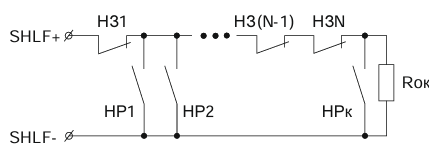
Figure 2. Wiring diagram of fire heat sensors for a “Fire” type zone
Diagram 2. Connecting Fire Smoke Sensors (type “Fire”)
-
D1…DN — sensor contacts
-
Rterm — terminal resistor 5.6 kΩ ±5%
-
RD1, RD2…RDN — additional resistors 2.2 kΩ ±5%
-
Maximum wire resistance: 470 Ω(see Figure 3)
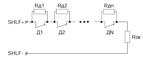
Figure 3. Wiring diagram of fire smoke sensors for a “Fire” type zone
Diagram 3. Connecting Fire Heat Sensors (type “Fire 2”)
-
D1, D2 — sensor contacts
-
Rterm — terminal resistor 4.3 kΩ ±5%
-
RD1, RD2 — additional resistors 6.8 kΩ ±5%
-
Maximum wire resistance: 470 Ω(see Figure 4)
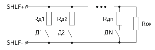
Figure 4. Wiring diagram of fire heat sensors for a “Fire 2” type zone
Diagram 4. Connecting Fire Smoke Sensors (type “Fire 2”)
-
D1, D2 — sensor contacts
-
Rterm — terminal resistor 5.6 kΩ ±5%
-
RD1, RD2 — additional resistors 2.2 kΩ ±5%
-
Maximum wire resistance: 470 Ω(see Figure 5)
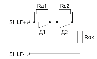
Figure 5. Wiring diagram of fire smoke sensors for a “Fire 2” type zone
5.3. Connecting Temperature Sensors
The following diagram is recommended for connecting DS18B20 temperature sensors:
-
D1…Dn — temperature sensors
-
Maximum number of connected sensors: 10(see Figure 6)
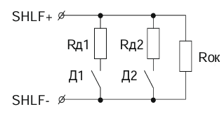
Figure 6. Wiring diagram of temperature sensors
5.4. External Connections
External connections of the TCMD include connecting power sources, backup batteries, sensors, and actuators.
The recommended external wiring diagram is shown in Figure 7.
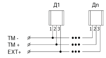
Figure 7. Recommended external connection diagram
6. LED Indication
The TCMD has LED indicators.
The table below shows the main LED indication modes for various states.
Table 2 — TCMD LED Indication
|
No.
|
State
|
Color
|
Effect
|
Frequency
|
Duration
|
|
1
|
Connection to server via Wi-Fi
|
Green–Blue
|
Pulsing
|
Slow
|
Continuous
|
|
2
|
Connection to server via GPRS
|
Green–Orange
|
Pulsing
|
Slow
|
Continuous
|
|
3
|
No connection to server
|
Red
|
Pulsing
|
Slow
|
Continuous
|
|
4
|
Zone Fault
|
White–Black
|
Blinking
|
Fast
|
30 s
|
|
5
|
Zone in ATTENTION mode
|
Orange–Black
|
Blinking
|
Fast
|
30 s
|
|
6
|
FIRE detected
|
Red–Black
|
Blinking
|
Very fast
|
60 s
|
|
7
|
Zone in ALARM state
|
Red–Blue
|
Color switching
|
Very fast
|
60 s
|
|
8
|
Arming delay timer
|
Green–Red
|
Color switching
|
Very fast
|
120 s
|
|
9
|
Zone armed
|
Green
|
Steady color
|
—
|
Continuous
|
|
10
|
Zone disarmed
|
Green
|
Steady color
|
—
|
Continuous
|
|
11
|
Zone armed, Wi-Fi connection
|
Green–Blue
|
Pulsing
|
Fast
|
Continuous
|
|
12
|
Zone armed, GPRS connection
|
Green–Orange
|
Pulsing
|
Fast
|
Continuous
|
|
13
|
Searching for wireless devices on Astra module
|
Light Green–Blue
|
Color switching
|
Slow
|
60 s
|
|
14
|
Searching for iButton
|
Light Blue–Purple
|
Color switching
|
Slow
|
60 s
|
7. Main Technical Specifications
Table 3 — Main Technical Specifications
|
No.
|
Parameter (unit)
|
Value
|
|
1
|
Number of connected Astra radio devices (pcs.)
|
Up to 32
|
|
2
|
Number of inputs (pcs.)
|
Up to 7
|
|
3
|
Number of 1-Wire type inputs (pcs.)
|
1
|
|
4
|
Number of outputs (open collector type) (pcs.)
|
Up to 8
|
|
5
|
Number of additional Touch Memory keys (pcs.)
|
Up to 25
|
|
6
|
Number of zones (pcs.)
|
Up to 10
|
|
7
|
Number of DS18B20 temperature sensors (pcs.)
|
Up to 10
|
|
8
|
Supply voltage (V, DC)
|
12
|
|
9
|
Current consumption (A)
|
2
|
|
10
|
External backup battery (V / Ah)*
|
12 / 7
|
|
11
|
Built-in battery (Li-Ion) (V / Ah)
|
3,7 / 1,8
|
|
12
|
Tamper protection type
|
Tamper sensor
|
|
13
|
Operating frequency of RI-M radio channel (MHz)
|
433,42
|
|
14
|
Radio signal range (m)**
|
Up to 100
|
|
15
|
Communication channels
|
GSM/GPRS (900/1800 MHz), Wi-Fi (2.4 GHz)
|
|
16
|
Number of SIM cards (pcs.)
|
1
|
|
17
|
Protection rating
|
IP20
|
|
18
|
Dimensions (mm)
|
160 × 160 × 39
|
|
19
|
Weight, max (kg)
|
0,64
|
|
20
|
Average service life (years)
|
8
|
|
21
|
Operating temperature range (°C)
|
–10…+50
|
|
22
|
Permissible humidity at +25 °C, without condensation (%)
|
Up to 98
|
Notes:
* The external battery is replaceable.
** Radio signal range is specified under conditions without obstacles (walls, doors, ceilings). Range may decrease in presence of interference or specific site conditions.
8. Package Contents
Table 4 — Package Contents
|
No.
|
Item
|
Quantity
|
|
1
|
GARM Link PRO Security Control and Monitoring Device
|
1 pc.
|
|
2
|
Battery A (Li-Ion), 3.7 V, 1800 mAh
|
1 pc.
|
|
3
|
Screw 3×30
|
4 pc.
|
|
4
|
Wall plug 6×30
|
4 pc.
|
|
5
|
Passport / User Manual
|
1 copy
|
9. Disposal Information
9.1. The TCMD does not pose any danger to human life, health, or the environment.
9.2. At the end of its service life, the device can be disposed of without requiring special environmental protection measures.
9.3. It is recommended to dispose of the battery by returning it free of charge to a retail organization, service center, manufacturer, or a specialized organization that accepts used batteries and power cells.
10. Warranty
10.1. The manufacturer guarantees that the TCMD meets technical specifications, provided the user complies with the conditions of transportation, storage, installation, and operation.
10.2. Warranty storage period — 5 years from the date of manufacture.
10.3. Warranty service period — 5 years from the date of commissioning, but no more than 5 years from the date of manufacture.
10.4. The average service life of the TCMD is 8 years.
10.5. During the warranty period, the manufacturer undertakes to repair or replace the TCMD.
10.6. The warranty does not cover cases of:
-
Non-compliance with the user manual
-
Mechanical damage to the TCMD
-
Repairs performed by persons not authorized by the manufacturer10.7. The warranty applies only to the TCMD. Equipment from other manufacturers used together with the TCMD (batteries, connection cables, etc.) is not covered by the warranty.10.8. The manufacturer is not responsible for any damage to health or property, as well as any direct or indirect losses resulting from improper use, malfunction, temporary inoperability of the TCMD, or claims by the user regarding the TCMD failing to perform its functions.