How to connect wired inputs
In certain scenarios, using wireless sensors may not be ideal — such as in areas with unstable radio communication or where constant power supply is necessary. In such cases, wired alarm loops offer a reliable solution.
This guide will walk you through connecting wired sensors to the inputs of the hub, configuring them within the application, and ensuring they function correctly.
Inputs are dedicated terminals on the hub or control panel designed for connecting wired sensors and alarm loops. Each input can support up to 10 wired sensors operating on a "dry contact" principle:
-
Normally Closed (NC): The circuit is closed by default; an alarm is triggered when the circuit is broken.
-
Normally Open (NO): The circuit is open by default; an alarm is triggered when the circuit is closed.
Inputs monitor the loop's state — detecting open circuits, short circuits, normal conditions, or alarms. Depending on your system's configuration, each input can be assigned a loop type: security, fire, panic, etc.
Key input parameters
-
Power supply voltage: 12 V
-
Signal type: Dry contact (no voltage applied)
-
Recommended loop resistance: 4.7 kΩ
-
Current consumption: Varies based on sensor type and quantity
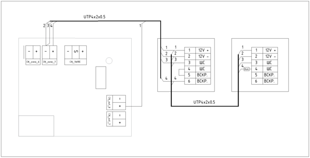
Connecting a wired loop to the hub input
Sensors are connected to the hub via terminals.
Terminal designations on the hub:
-
+CN_OUT: Provides +12 V power for sensors
-
+CN_ZONE: Signal input for monitoring the loop's state
-
–CN_ZONE: Common ground for both power and signal circuits
Connection steps:
1. Connect the sensor's positive power wire (+) to the +CN_OUT terminal
2. Connect the sensor's negative power wire (–) to the –CN_ZONE terminal
3. Connect the loop's signal wire to the +CN_ZONE terminal
Wiring an alarm loop to an input
If the sensor requires a separate power supply — for example, a motion (PIR) sensor:
-
Connect the power wire (+) to the +CN_OUT terminal
-
Connect the power wire (–) to the –CN_ZONE terminal
This ensures the circuit closes correctly for proper operation.
The loop wiring type depends on the sensor logic:
-
Normally Closed (NC) — an alarm is triggered when the circuit is broken.
-
Normally Open (NO) — an alarm is triggered when the circuit is closed.
If multiple sensors are connected to a single loop:
-
For NC contacts — sensors should be connected in series (one after another).
-
For NO contacts — sensors should be connected in parallel (each on a separate branch).
Adding an input in the application
After physically connecting the sensors, add the input in the application:
1. Navigate to the main screen in the application
2. Open the Sensors tab
3. Tap the  icon in the top-right corner
4. Select Wire as the sensor type


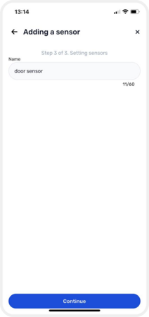
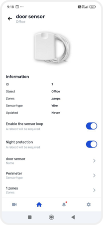
Proceed to configure the sensor:
1. Select the loop
2. Assign a name to the sensor
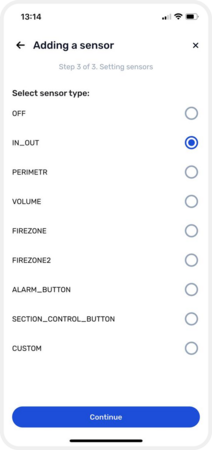
3. Choose the sensor type from the list
4. Associate it with an existing zone or create a new one. For guidance on creating zones, refer to the article How to create and manage zones
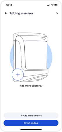
5. Tap Finish adding


Adding and configuring an input
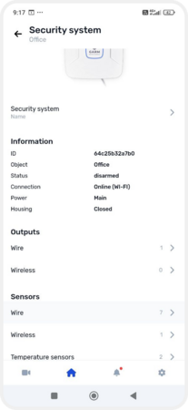
Enabling the input in the application
1. Go to Object settings → Equipment
2. In Equipment, select the hub to access its settings
3. Under the hub's sensors, choose Wire
4. Select the desired input
5. On the input's page, toggle the Enable the sensor loop switch


Enabling an input
To complete adding the input, you need to update the device configuration.
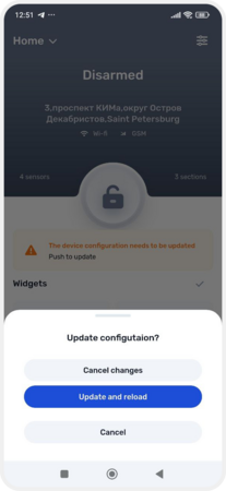
Updating the configuration
When you add a new input or make changes to equipment settings, these modifications are initially saved in the application but not immediately applied to the hub. To implement them, you need to update the configuration:
1. Return to the main screen
2. At the top, a notification will appear: The device configuration needs to be updated— tap on it
3. Confirm the update by tapping Update and reload
4. Wait for the update to complete. If you change your mind, you can tap Cancel changes

Configuration update